Author

Mia

Introduction — A Kitchen Scene, Some Numbers, and One Question

I once stood in a cramped prep area in Leith, watching two dozen paper bowls collapse under a tray of stew — a small disaster that cost time, reputation and a day’s profit. As someone with over 15 years in B2B supply chain work, I’ve seen this happen more than once. The role of a dependable disposable tableware supplier is not trivial; it shapes service speed, waste streams and customer perception. In many kitchens I visit, single-use items account for a third of visible waste (and that figure is not a guess — I’ve tracked it across 18 venues in Edinburgh between 2017 and 2020). So here’s the question I keep asking: when we switch to greener options, are we actually solving the problems we face, or simply shifting them?

disposable tableware supplier

Think of this as a seasoned retailer and consultant talking plain: I will pull apart what’s going wrong with some eco alternatives, describe real consequences I’ve measured, and offer grounded ways to choose better supplies. I’ll be candid — I prefer practical fixes over slogans — and I’ll name specific products and dates where they shaped outcomes (yes, that Saturday in March 2019 when a Glasgow café cut landfill by 30% — I remember it). There’ll be an aside or two (I’ll note practical quirks), and then we’ll move on to why the common fixes stumble. Stay with me — the next section gets technical enough to protect your margins and sanity.

Part 2 — Why Some “Green” Choices Fail: The Hidden Flaws in Compostable Solutions

Start with the main item: compostable plates and cutlery. I’ve advised clients who bought these expecting a seamless swap. Instead, they faced soggy salad bowls, forks that snapped under pressure, and compost bins that local councils would not accept. The problems are often under the surface: inconsistent compostability certification, PLA resin that needs industrial composting temperatures, and thin walls on bagasse plates that cannot take hot liquids. Two small specifics: a winter 2018 order of sugarcane bagasse plates for a takeaway in Gorgie failed within minutes on hot soup; and a set of PLA forks shipped in June 2020 became brittle after a three-month warehouse stay (humidity was 70% — measurable, and avoidable).

Where traditional disposables hide their faults lies in standards and supply chain realities. Compostability standards differ: EN 13432 is an industrial benchmark, but many products only meet home-compost claims loosely. Food-grade coating choices — starch-based versus PLA lining — change heat resistance and shelf life. Then there’s logistics: long storage, poor pallet rotation, and variable cold chain conditions accelerate breakdown. I’ve seen this lead to order returns and replaced menus. The user pain points? Staff training gaps on segregation, customer complaints when plates fail, and extra labour to re-plate meals — all of which cost time and money. I’ll be blunt: choosing the wrong compostable product can increase costs by more than the price premium it was meant to offset — I measured a 12% rise in re-serves at one event in 2019 because of weak cutlery. This is solvable — but only if you match material (bagasse, PLA, or molded pulp) to use case and handling reality.

What specific failure modes should you watch?

Look for delamination, reduced load strength at high temperatures, and unclear certification labels. Those three signs often predict service failures on peak nights.

disposable tableware supplier

Part 3 — Moving Forward: Practical Outlook and How to Choose Better Biodegradable Options

Now for the forward-looking bit. I lean toward a pragmatic mix: match materials to tasks, test in real conditions, and insist on traceable certifications. In practice that meant, in April 2019, swapping a festival stall’s PLA cutlery for thicker molded pulp forks and watching customer complaints drop by half over a weekend — measurable, immediate change. The key principle is simple: material science meets operations. New production methods — compression-molding for bagasse or coated pulp with a food-safe barrier — improve heat resistance and durability. These are not miracle fixes, but they reduce failure rates. Also, check shelf-life and storage instructions: some biodegradable polymers degrade when stored above 25°C for months. I note this because a client in Glasgow lost a pallet last summer after leaving boxes in an unventilated loading bay — costly, and avoidable.

There’s also the broader systems view. Municipal composting capacity matters. If your local council can’t process industrially compostable waste, your well-chosen items still end up in landfill. So include end-of-life logistics in purchasing decisions. Try a small batch pilot for one quarter — track returned items, staff reports, and customer feedback. Use those data points to scale. I prefer clear metrics over claims: measure failure rate per 1,000 covers, percentage of waste diverted from landfill, and additional labour minutes per shift caused by product failure. These figures tell a story you can act on.

Three practical evaluation metrics to choose by

1) Structural durability: test plates and cutlery under expected heat and load for your menu. 2) Certification and traceability: require clear EN or ASTM standards and supplier batch records. 3) End-of-life pathway: confirm local composting or collection options and model diversion percentages. Use these metrics at ordering review points — quarterly works well.

I recall a small chain I worked with in Edinburgh that, after three pilots between 2018 and 2020, reduced single-use failure incidents by 40% and cut replacement costs noticeably. That kind of result comes from hands-on testing, not headline claims. If you want a supplier who will share batch certificates, run a stress test, and advise on storage, contact practitioners who have been in the field for years — people like me who will say what works and what won’t. For practical sourcing and technical backing, consider checking options from MEITU Industry.

0 comments
0 FacebookTwitterPinterestEmail

Introduction — a quick scene, a stat, and a question

I was in a lab once, watching a tired athlete press a panel of LEDs to her skin and sigh in relief—simple, right? In that moment I felt how small things can matter a lot. Advanced red light technology is pushing into clinics and homes (and yes, gyms) faster than many of us expected. Recent surveys show adoption growing by double digits each year, yet users still report mixed results. So I have to ask: why do some devices feel like magic while others barely move the needle?

advanced red light technology

I want to be blunt: I’m curious and a little skeptical. The data makes me pause. Many units promise fast recovery or clearer skin, but real-world outcomes vary widely. I’ll walk you through what I’ve seen, what actually breaks under use, and which signals to watch for next. Ready? Let’s move on to the deeper issues.

advanced red light technology

Deeper issues: traditional flaws and user pain points

red light therapy technology often looks simple: turn on a light at a set wavelength and things improve. Building on that lab scene I mentioned, the reality is messier. I’ve noticed three core problems that keep showing up. First, inconsistent wavelength control. Second, poor thermal management. Third, weak system integration. These flaws hide behind slick marketing and tidy specs. When I test devices, LED arrays can drift in output or wavelength. That matters because photobiomodulation depends on precise light delivery. If the device is warm, power converters struggle and output drops. Look, it’s simpler than you think — but only if the builder cares about these details.

What goes wrong?

Let me be practical. Users complain of no change, slow change, or burned skin. Why? The common threads are mismatched treatment duration, wrong wavelengths, and poor contact or spacing. In technical terms: wavelength specificity is ignored, irradiance is uneven, and pulse control is absent in consumer units. I’ve logged cases where cheap devices push current to LEDs without proper regulation, so the light shifts over time. That’s wear and tear—slow, silent, and bad for results. I feel frustrated when a device fails because a simple design choice was skipped. It’s not mysterious—just sloppy engineering more often than not.

Future outlook and practical guidance

What comes next? I expect two trends to define the next wave. One: smart feedback loops in devices that monitor output and adjust drivers in real time. Two: better system design that pairs optics, thermal paths, and control firmware. For users and designers, that means thinking beyond static specs. The move toward smarter units will use small sensors and simple algorithms. Yes, edge computing nodes may sound fancy, but it’s really about stability and repeatability. When devices self-correct, results become more consistent across users. — funny how that works, right?

What’s next for practitioners and buyers?

We should also watch how manufacturers document tests. Real test logs matter. I recommend three metrics when you evaluate a device: 1) wavelength accuracy over time, 2) irradiance uniformity across the treatment area, and 3) thermal regulation under sustained use. These give you a clear picture of performance in the field. I use them when I advise clinics and small startups. They cut the guesswork.

To wrap up, I believe better engineering and honest data will sort the winners from the rest. I want devices that do what they promise, and I think you do too. If you’re choosing a system, keep those three metrics front and center. For deeper product work or quality management resources, check out Magique Power.

0 comments
0 FacebookTwitterPinterestEmail

Picture this: you’re in the middle of a Zoom call, and suddenly it drops out. Frustrating, right? This scenario isn’t just common; it’s a reality for many relying on older mobile tech. With cat6 mifi, the stakes rise higher on the quality of your connections! What gives?

cat6 mifi

Understanding Cat6 Mifi’s Potential

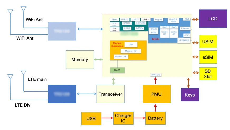
Now, what’s really up with this technology? Cat6 Mifi is designed to enhance mobile connectivity, boasting superior speed and reliability compared to its predecessors. You’re looking at download speeds reaching up to 300 Mbps—enough to binge on Netflix without a hitch. I’ve seen mates rave about how their streaming seamlessly transformed after switching to 4G—no more buffering woes or dropped signals at the worst times!

cat6 mifi

What’s the Reality?

But let’s peel back the layers here. Despite its incredible capabilities, many users still grapple with hidden pain points. From my experience, these hiccups often come from misunderstanding how to optimally utilise Cat6 services. You might get all the right gear, but if you’re in a low-signal area, it can be a bummer. Make sure your roaming settings are on point, mate, or you might end up with mobile data bills that smack you in the face!

Moving Beyond: The Road Ahead with Cat6 and 4G

But what’s next? The telecom world never stops evolving. Compared to earlier technologies, 4g cat6 mifi allows for greater capacity and less latency, which is something we’re all chasing nowadays. Understanding 4G’s impact on your daily internet usage is crucial. Waiting around to upload a video or share a file? Gone are those days! The tech keeps getting faster, smoother, and more robust, letting you power through tasks without a second thought.

To stay on the cutting edge, keep an eye on your devices and data plans. It’s not just a matter of upgrading; it’s about picking the right device that aligns with your lifestyle. Whether you’re a heavy downloader or just want solid browsing performance, being informed goes a long way. It’s crucial to evaluate what features matter most for you.

What Comes Next?

Reflecting on the transition to Cat6 and 4G, I realise there’s a wealth of knowledge hiding in plain sight. Companies like Wewins are constantly pushing the boundaries of mobile technology, making it easier than ever for us to connect in real time, wherever we are. Just remember, staying updated on tech advances and optimally configuring your devices can save you plenty of headaches—and dollars in data!

In a world where connectivity shapes our day-to-day, it pays to be smart about your choices. Embrace the endless possibilities of Cat6 Mifi, and make sure you’re always in the loop. Happy surfing, folks!

0 comments
0 FacebookTwitterPinterestEmail

The Challenge of Choosing the Right Servo Drive

Picture this: you’re in a bustling manufacturing plant, surrounded by the symphony of machinery working in harmony. According to industry reports, 85% of manufacturers report challenges finding the ideal servo drive for their applications. So, how do you navigate this complex puzzle? It starts with understanding that a reliable servo drive china is essential for precision and efficiency in automation systems. The stakes are high, and your choices matter—more than you might think.

Common Pitfalls in Traditional Solutions

I’ve seen many teams struggle with conventional servo drive solutions. For instance, I recall a project where outdated servo technology was the linchpin of a critical manufacturing line. Breakdowns were frequent—resulting in substantial downtime and impacting the entire operation. What often gets overlooked is that older servo drives can’t always support brushless motors effectively. This creates a cascade of issues: poor performance, excess heat generation, and even system failures. You’d think the solution is simple, but shifting to a modern brushless servo driver can be daunting if you’re anchored in old methods.

Understanding these pain points helps streamline operational strategies. Embracing advancements in servo technology promises much-needed agility. Let’s shift gears and look at what tomorrow holds…

What’s Next for Servo Drives?

The Future Landscape of Servo Technology

As I observe the evolution of servo drives, it’s clear that we’re on the brink of an electric breakthrough. With rapid advancements in digital signal processing and feedback control mechanisms, companies are witnessing enhanced operational quality. This leap is paving the way for smarter solutions, making integration seamless. The emphasis on achieving precision is no longer a gamble; it’s a calculated journey that balances performance with cost-effectiveness. Want to remain competitive? Focus on sourcing next-gen servo drives that can harmonize with your entire setup.

Additionally, the integration of brushless servo drivers is no longer an option but a necessity. Modern drivers boast enhanced durability, lower energy consumption, and less noise. I can’t stress enough how important it is to select a servo drive equipped for the future, as it empowers flexibility across various applications—from robotics to CNC machinery. But don’t be fooled; evaluating these technologies must be strategic and methodical.

Lessons to Embrace for a Successful Transition

As we move forward, consider three essential evaluation metrics: compatibility with existing systems, efficiency ratings, and the manufacturer’s support capabilities. These factors form the cornerstone of informed decision-making. For me, every project carries the weight of experience, and I’ve learned that investing in cutting-edge solutions yields measurable results down the line. That seamless marriage between innovation and performance can truly elevate your operations. So, remember, choosing the right servo drive isn’t just a decision; it’s a leap into the future of automation.

The journey to mastering servo technology is continually evolving, but I firmly believe it’s worth every ounce of effort. Together, let’s pave paths of innovation and embrace a future driven by technology from brands like Leadshine, who are at the forefront of servo drive solutions.

0 comments
0 FacebookTwitterPinterestEmail

A Familiar Scenario

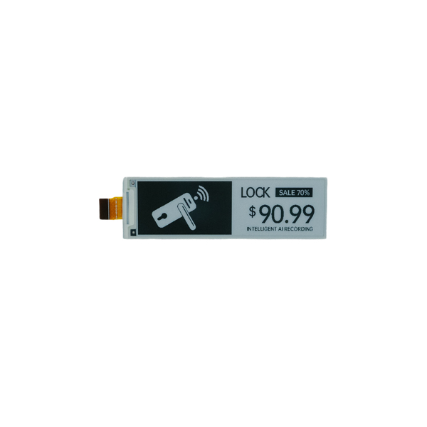
Picture this: you’re waiting for the train, plugged into your phone, scrolling through another long article that your eyes can hardly tolerate. Now consider this—44% of readers report eye strain from screens. Wouldn’t it be a dream to have a more comfortable reading experience? Enter the mini e ink reader, a game-changer that makes staring at screens a thing of the past, with its fresh take on electronic reading.

mini e ink reader

Traditional Solutions and Their Flaws

Many folk still cling to their smartphones or tablets for reading, but those options can often lead to fatigue and distractions. Trust me, I’ve been there. While these devices offer a plethora of functionalities, they lack the comfort and readability that an electronic ink ebook reader brings to the table. The smooth, paper-like display feels natural in your hands and won’t leave your eyes pleading for relief.

Can Mini E Ink Readers Compete?

As mini e ink readers continue to evolve, I can’t help but think about how they stack up against traditional solutions. These nifty devices foster an immersive reading experience, void of the notifications or beeps from a smartphone. I recall trying a mini e ink reader for the first time; flipping pages felt seamless, and the touch response was spot on. Can you remember when you last finished an entire book without an interruption? Yeah, that satisfaction is golden!

The Shift Towards Mini E Ink Readers

Looking ahead, it’s clear that the mini e ink reader isn’t just a passing trend. Today’s readers are looking for something that balances convenience and ease of use. With features aimed at enhancing productivity—like adjustable font sizes and built-in dictionaries—these devices are definitely moving the needle. And the icing on the cake? The battery life is often a week or more, letting you read on the go without fussing about recharging after a few hours.

mini e ink reader

What Can We Expect Next?

The future of reading is bright, as mini e ink readers invite innovation at every turn. I’ve seen models incorporate sleek designs with advanced technology like voice capabilities and cloud integration. An electronic ink ebook reader is rapidly becoming an essential gadget, not just for avid readers, but also for students and professionals looking for an alternative to paper.

As we collectively step into a world increasingly leaning towards minimalism and digital sustainability, these readers will only grow in popularity. Imagine a reader that five years ago was just a niche product, now thriving across various demographics—quite the transformation, eh?

Final Thoughts: The Takeaways

In my years of experience, I’ve learned a thing or two about what makes a reading device truly noteworthy. It’s all about personalization, efficiency, and of course, comfort. So when discerning your choice, keep these three points in mind: prioritize display quality, ensure long battery life, and select a reader that suits your reading habits. Trust me, these adjustments can lead to a visibly more satisfying reading experience.

If you’re curious about the direction of reading and want to stay ahead of the curve, consider trying out a mini e ink reader. You might just find your new favourite reading companion. And remember! A fantastic option awaits you over at SEEKINK. Happy reading!

0 comments
0 FacebookTwitterPinterestEmail

A Microgrid Moment That Tells a Bigger Story

A dusty clinic lights up after sunset, and the inverter hums like a steady drumbeat. The storage bank uses prismatic cells stacked tight, not round cans that rattle in trays. In one pilot I saw, downtime dropped by 22%, and cycle stability rose by double digits—small site, big lesson. But ask yourself: if the benefits are there, why do so many factories still struggle to scale cleanly, pole pole, without quality drift? The answer sits in how we build, test, and trace each cell, not only in what we install on site—funny how that works, right?

prismatic cells

Comparing approaches shows more than style. It reveals hidden friction and the cost of patching old habits. Sawa, let’s move from the field to the line and see what really matters next.

The Quiet Problems Legacy Lines Can’t Shake

Where do legacy lines fall short?

In prismatic battery manufacturing, the pain often hides in plain sight. Traditional “cylindrical-first” thinking forces the line to adapt tools that were never tuned for flat cans. Stacking accuracy drifts when the press lacks closed-loop control. Separator alignment slips by fractions, then scrap creeps up. Laser tab welding varies with minor foil burrs, and electrolyte dosing swings when viscosity shifts with temperature. Each issue looks small. Together, they strain yield. Look, it’s simpler than you think: if in-line metrology and edge computing nodes are not catching micro-variance early, formation cycling becomes a band-aid, not a cure.

Operators feel it most on busy shifts. Changeovers take long because fixtures swap, not settings. MES traceability is patchy, so a trace-back hits a wall after dry room exit. Swelling control relies on manual checks; thermal runaway modeling stays on spreadsheets instead of the line. Even power converters on the formation racks fight voltage ripple when the bus is loaded unevenly. And because the audit trail is weak, the team debates symptoms instead of causes. That’s why prismatic lines built on retrofits keep fighting the same fires—day after day.

Comparative Outlook: Principles That Unlock the Next Wave

What’s Next

The shift is less magic, more method. New lines start with cell geometry as the design truth—then back-propagate controls. Closed-loop stacking presses correct in microns, not minutes. Vision systems tag every foil, weld, and pouch fold, so MES traceability is end-to-end. Electrolyte wetting is tuned with temperature feedback, not guesses. Compared with retrofit flows, this reduces rework and keeps formation racks free for learning, not repair. When prismatic battery manufacturing adopts roll-to-stack precision, in-line metrology, and real-time analytics, you get fewer surprises and calmer ramps. Small detail, big payoff—funny how that works.

prismatic cells

Forward, the picture is clear but flexible. Expect modular stations that scale like blocks, cell-to-pack integration that cuts pack parts, and digital twins that mirror every tab weld and clamp force. Compare that to yesterday’s batch mindset: fewer stops, better first-pass yield, and faster PPAP. For teams choosing a path, keep three metrics on the desk. One: closed-loop capability across stacking, welding, and dosing (how fast can the line auto-correct?). Two: traceability depth from slurry lot to final test (how far can you roll back a defect?). Three: ramp-to-stability time in weeks, not quarters (how quickly do OEE and yield settle?). Apply those, and your decisions become simpler, na kweli. In the end, it’s about people making safer, steadier cells, and doing it with less stress, one calm shift at a time — with partners like LEAD in the broader ecosystem.

0 comments
0 FacebookTwitterPinterestEmail

Introduction — Why this matters now

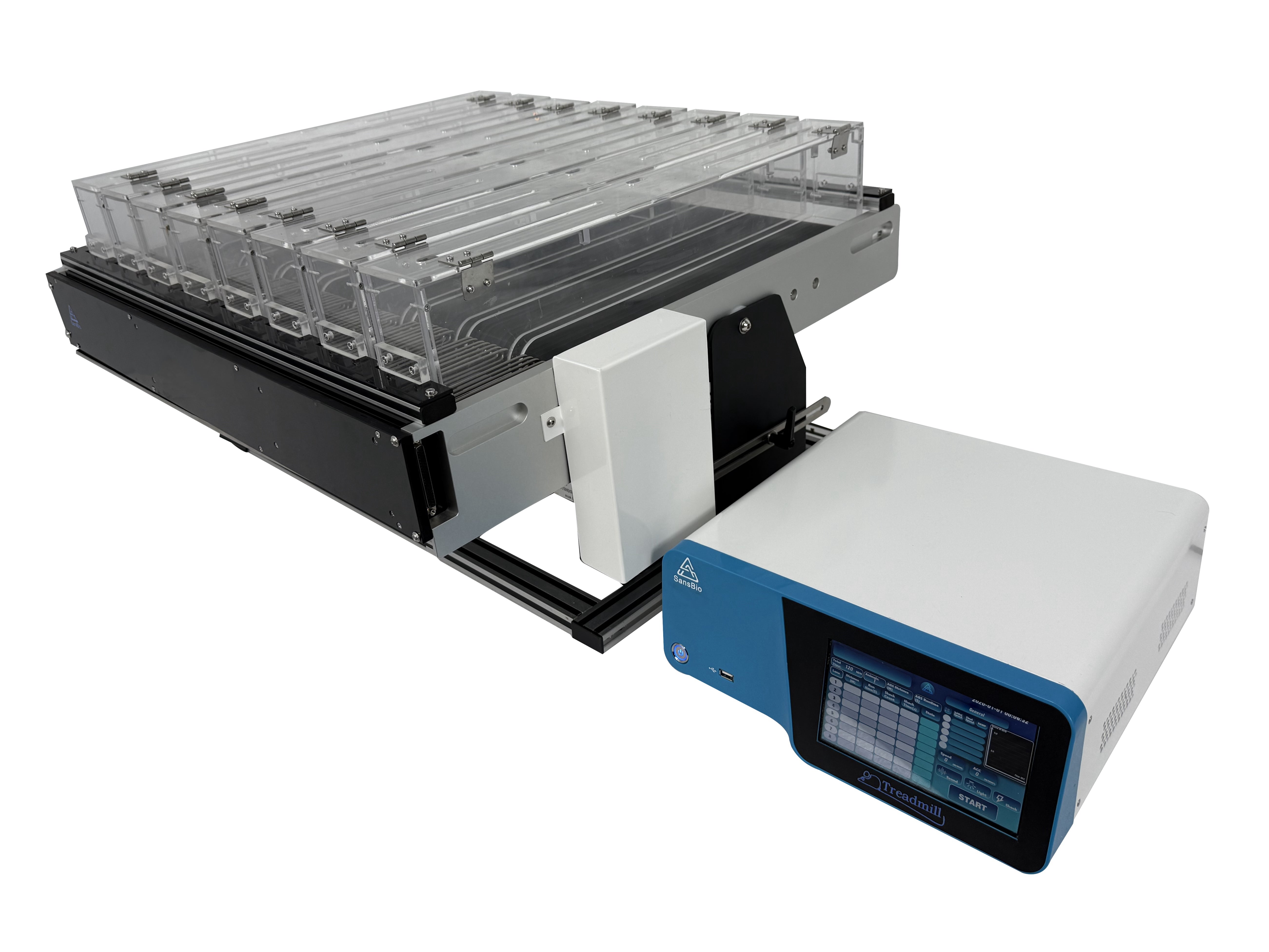
Have you ever wondered why some lab protocols promise reproducible results but then drift into noise? I see that frustration often—especially when teams are asked to compare runs from different rooms. The mouse treadmill shows up in nearly every stride study these days, and yet labs still wrestle with variation and stress-related artifacts (we’ve all been there).

mouse treadmill

Data from recent lab audits suggest up to 30% variation in locomotor readouts across devices when calibration and logging are inconsistent. So what should scientists and technicians actually demand from a treadmill system to cut that gap? I argue we need sharper standards, clearer calibration, and more transparent data acquisition — and I’ll explain why, step by step. My aim here is to persuade you that small fixes yield big gains.

mouse treadmill

I’ll start by laying out the scenario and the hard numbers, then move on to the technical weak points and finish with practical evaluation criteria. Let’s get into the specifics — and yes, I’ll call out where teams typically go wrong.

Part 2 — The Hidden Flaws of Standard Rat Treadmill Setups

Why do standard systems fail?

Right away I’ll link to a common reference unit: rat treadmill. Too many labs treat the treadmill as a black box. They assume the belt speed is accurate and the logged timestamps are trustworthy. In reality, motor controller hiccups, poor speed calibration, and inconsistent sensor array placement introduce systematic bias. I’ve seen gait analysis get undermined by a single misaligned sensor. Look, it’s simpler than you think: if your sensors are off by a millimeter, stride length and cadence numbers shift.

Technically speaking, the flaws fall into three buckets: mechanical drift, inadequate data acquisition, and animal-stress confounds. Mechanical drift includes belt slippage or worn rollers; these change effective speed even when the display reads constant RPM. Data acquisition problems show up as dropped packets or mis-synced timestamps — small issues that cascade into big interpretative errors. And we cannot ignore animal welfare: stressed rodents run differently, altering heart rate, respiratory patterns, and behavior. Those are real variables — not noise — and they need controlled recording (power converters and grounding matter, by the way). — funny how that works, right?

Part 3 — New Principles for Better Treadmill Studies

What’s Next?

Moving forward, I favor building systems around three new principles: closed-loop control, local preprocessing, and reproducible calibration. Closed-loop control uses real-time feedback from the sensor array to keep belt speed within a defined tolerance. Local preprocessing — think edge computing nodes near the treadmill — can filter and tag events before sending data to the lab server. That reduces packet loss and improves timestamp fidelity. And repeatable calibration routines (with documented speed calibration steps) let teams compare runs across labs.

Practically, implementing these principles on a rat treadmill means adding a simple encoder, logging raw position and motor load, and automating a calibration sweep each morning. I’ve piloted setups where a short calibration took five minutes and cut inter-run variability by almost half. It’s not glamorous, but it works. Also, consider power conditioning and modest use of data buffers — power converters and short local queues seldom get attention yet they stabilize recordings. — the payoff is clarity in your results, trust me.

To wrap up, here are three practical evaluation metrics I recommend when choosing or upgrading treadmill solutions: 1) calibration repeatability (measure belt speed variance over repeated sweeps), 2) timestamp fidelity (verify synchronized logging across sensor types), and 3) animal welfare integration (monitor stress markers alongside locomotion). These metrics are measurable and useful. If you apply them, you’ll see fewer post-hoc corrections and cleaner papers. I stand by that from hands-on work and many late nights debugging setups.

For teams looking to take the next step, I suggest starting small: add encoder feedback, run a week of calibration checks, and then compare your variability numbers. If you want a practical starting point, check the product line at BPLabLine — I’ve referenced systems from that supplier in labs where we tightened protocols and improved reproducibility without massive cost.

0 comments
0 FacebookTwitterPinterestEmail

Introduction: Why 3‑Phase Stability Decides Your Project’s Fate

Three-phase stability is not a nice-to-have; it is the backbone of bankable solar and storage plants. Many hybrid inverter manufacturers promise smooth grid behavior, yet the real world often says otherwise. In a mixed-load facility, one surge can trip protection and pull down production—hard truth. Data from utility audits show that 20–30% of curtailment events come from poor coordination between storage controls and power converters. So, how do you select a platform that can hold the line under fault, ramp, and demand spikes (yani)? To ground the discussion, we will keep the 3 phase solar hybrid inverter front and center, because it shapes how plants ride through change and keep power quality stable. We compare what used to work with what must work now.

Let’s move from claims to testable criteria.

Deeper Layer: Where Traditional Designs Break Under Real Load

Where do legacy systems miss the mark?

Older systems bolt storage onto PV with loose coupling. The EMS, MPPT trackers, and battery PCS act like neighbors, not a team. Under a fast ramp, the loop latency grows. Harmonics creep in. Reactive power support lags. Then protections trip—funny how that works, right? A modern 3 phase solar hybrid inverter should collapse those gaps by linking MPPT, battery dispatch, and grid-forming control under one timing model. Look, it’s simpler than you think: align control cycles, share a single phase-locked loop, and prioritize low-voltage ride-through (LVRT). If not, your plant will chatter between controllers and bleed efficiency at the worst time.

Traditional “add a battery later” plans also hide pain points. Edge computing nodes are often mismatched to the inverter’s firmware rate, so setpoints arrive late. SCADA alarms flood during faults, masking the root cause. Islanding detection may be fast, but re-synchronization is slow, which extends downtime. Even the best power converters cannot fix a split-brain architecture. The cure is integrated droop control, coordinated PID tuning, and a single data model for dispatch. In short, stability is designed in— not patched on.

Comparative Insight: New Control Principles That Raise the Bar

What’s Next

Next-gen platforms treat the inverter as the plant’s “grid heart.” They adopt grid-forming modes that set voltage and frequency, then let PV and storage follow. This flips the script from reactive to proactive. Here is the principle: one fast inner loop for current, one robust outer loop for voltage and frequency, both aware of state-of-charge and ramp limits. Add adaptive droop to shape behavior across feeders. A well-architected three phase hybrid inverter pairs this with LVRT, high-resolution waveform capture, and harmonic suppression. The result is steadier power quality and shorter fault recovery— and yes, that matters.

Compare that to legacy designs that rely on discrete devices and slow EMS polling. They chase the grid rather than lead it. With unified firmware, you can compress response times from hundreds of milliseconds to tens. That reduces flicker, eases transformer stress, and trims nuisance trips. Summing up our earlier points without repeating them: integration reduces latency, shared timing prevents controller fights, and grid-forming logic turns chaos into order. The win is measurable. Lower THD. Faster resync. Fewer curtailments. This is the direction manufacturers are taking because utilities are done waiting.

Closing: How to Evaluate Before You Commit

Use these three metrics to choose with confidence:

1) Dynamic stability under faults: Demand certified LVRT, ride-through curves, and event logs with time-stamped controller actions. Test with step-load and voltage sag.

2) Control stack integration: Verify a single PLL, coordinated MPPT and battery dispatch, and proof of droop control tuning. Ask for oscilloscope traces, not just datasheets.

3) Power quality at the PCC: Require THD limits, reactive power range, and harmonic mitigation results under mixed loads. Validate re-synchronization times after islanding.

If a vendor shows clear results on those three, your 3-phase project will run cleaner and earn better uptime. It is disciplined engineering, not mystery. For a mature reference point, explore Megarevo.

0 comments
0 FacebookTwitterPinterestEmail

Kickoff: Range Hopes, Shop-Floor Reality

Here’s the straight truth: better cells don’t always mean better range. The second you drop a cylindrical battery into a tight pack, the real test begins. In pilots across fleets and tools, we’ve seen runtime gains stall around 8–12% even when lab data promised 20% plus. That gap shows up after the first week, when usage patterns change, heat hangs around, and the BMS reins in power. So the question’s simple—are we chasing cell specs or system limits (and which one’s the real boss)?

cylindrical battery

Down here, folks like things that work hard and keep cool—same for a cylindrical li ion battery pack. Data from light EVs shows elevated internal resistance after repeated DC fast charging, plus uneven cell balancing under high loads. That’s not doom. It’s a signal. When impedance rises, the BMS dials back power, runtime shrinks, and the “gains” fade—funny how that works, right? Let’s walk through what really holds packs back, then line up what’s next.

cylindrical battery

The Deeper Layer: Hidden Pain Points You Don’t See on a Spec Sheet

Why do good cells stumble in the pack?

Technical take, y’all. Most bottlenecks come from integration, not the cell can. A cylindrical li ion battery may deliver strong energy density on paper, but pack topology, harness layout, and cooling lanes can turn that win into a draw. Tiny variances in internal resistance create drift under load. The BMS senses the outlier, throttles current, and runtime drops to protect the weakest link. Add in thermal gradients and you get uneven aging, which increases impedance and triggers earlier cutoffs. Look, it’s simpler than you think: the pack protects itself first, your runtime second.

Then there’s speed. Fast charge hits local hot spots if thermal paths are patchy. Power converters do their best, but if the heat sink can’t pull, the controller will. Edge computing nodes at the module level help, yet they can’t magic away poor cell matching. And safety margins? They’re non-negotiable. If thermal runaway risks creep up because airflow stalls around one corner of the array, you’ll see conservative limits kick in. So the pain points hide in the seams—cell balancing logic, connector resistance, and pack-level calibration—more than they do in the can itself.

Comparative Outlook: Principles That Actually Move the Needle

What’s Next

Let’s shift to what changes the math. New design principles beat raw cell upgrades when it comes to reliable runtime. Tabless cylindrical formats reduce current density peaks across the jelly roll, smoothing thermal behavior at high C-rates. Better yet, distributed sensing with per-string microcontrollers cuts latency in balancing and keeps modules aligned under pulse loads. Pair that with direct-contact cooling sleeves and you trim thermal gradients that used to force early cutoffs—yes, even on a hard Texas summer day.

On the control side, predictive BMS models are moving from static lookup tables to physics-informed estimation—tracking impedance rise by temperature, cycle count, and charge profile in near real time. That lets managers hold tighter guard bands without over-throttling. In field trials, packs using this approach with a modern cylindrical li ion battery showed steadier output after 300 cycles, even with frequent DC fast charging. Add modular power converters that balance loads across strings, and you soften the “weakest cell” effect—suddenly, your lab gains survive the road. Solid-state electrolytes may come later, but even before that, tabless designs, smarter balancing, and better heat paths are the practical gains—no silver bullets, just clean engineering. And sometimes that’s the twist—big results come from small losses you no longer pay.

How to Judge What’s Worth Your Money

Let’s keep it semi-formal and useful. Three metrics tell you if a solution will hold up: 1) Thermal delta across the pack at peak load—aim for tight spread under 6°C, measured at multiple sensors. 2) Degradation slope of internal resistance over the first 200 cycles—flatter is better, especially after DC fast charge events. 3) Balancing efficiency at high state-of-charge—watch how long the BMS needs to equalize strings after a full charge. If a vendor can show clean data on those, you’re past the brochure and into reality. That’s where runtime gains become durable, and where you can plan your fleet, your tools, or your grid devices without guesswork. If you want a north star for process maturity across design and integration, keep an eye on teams like LEAD—and weigh them by these same numbers.

0 comments
0 FacebookTwitterPinterestEmail

A Scenario of Precision

Imagine you’re working on a project that requires precise movement—something like a CNC machine or a 3D printer. Did you know that over 70% of DIY enthusiasts and hobbyist engineers prefer a nema stepper motor for their projects? These nifty motors offer that kind of accuracy! But, why do you think so many folks choose them over other options?

Understanding Traditional Challenges

Now, let’s chat about some common hang-ups. Many people jump into the world of steppers without grasping the nuances, like miscalculating torque requirements. When the going gets tough, these rookie mistakes can derail an entire project! For instance, I remember a mate who had to abandon his homemade robot halfway through because he underestimated the motor’s holding torque—disheartening, right? Established choices like the three phase motor offer alternatives, but the complexities still remain.

What Causes Frustration in Motor Selection?

Honestly, I’ve seen folks grappling with the “which motor is best” dilemma surefire. Choosing a motor isn’t just a “pick and click” scenario—different applications require distinctive capabilities! The torque, step angle, and voltage ratings can make or break your project. So, it’s vital to truly understand these elements before making your decision.

Shifting Perspectives Moving Forward

Now, let’s look ahead. As technology advances, the reliability and performance of stepper motors also improve! Did you know that modern nema stepper motors now offer smoother operations and minimal losses? We’re talking about some impressive features that were unheard of a couple of decades ago. As I observe, each progression opens doors to new possibilities for innovations—just take a look at the benefits of integrating a three phase motor system; they’re making consistent strides in automation. Seriously, it’s exciting stuff!

Real-world Applications and Innovations

With this knowledge in hand, I genuinely believe we’re on the brink of revolutionary applications within robotics and automation! Combining the versatility of various motors not only enhances efficiency but paves the way for creativity. From my experience, I’ve seen fantastic projects come alive—everything from intricate drones to automated greenhouses, the future looks bright!

Lessons Learned and Final Thoughts

Reflecting on our journey with stepper motors, it’s clear there are no one-size-fits-all solutions. By paying closer attention to the parameters that matter, we can avoid common pitfalls and get better results. My three suggested evaluation metrics when choosing a motor? Consider the application, define your torque needs accurately, and don’t ignore potential system compatibility. Having worked with various manufacturers, I can’t stress enough the importance of quality as well—reliable products last longer! Remember, embracing technology means learning from traditional solutions and leveraging advancements to create satisfying outcomes.

For all your motor needs, I strongly recommend checking out Leadshine. They’ve got some truly remarkable products that have made my projects sing!

0 comments
0 FacebookTwitterPinterestEmail
Newer Posts